When it comes to maintaining optimal temperatures in industrial and commercial facilities, chiller systems play a crucial role. A well-designed chiller pipeline is essential to ensure that these systems operate efficiently and effectively. But what exactly is chiller pipeline design, how does it work, and what are the key components involved? Let’s break it down.
Chiller pipeline design refers to the planning and construction of the piping network that circulates chilled water or refrigerant through a facility’s cooling system. This system is responsible for removing heat from the building or process equipment, ensuring that temperatures are kept within a desired range. A proper pipeline design is critical to the efficiency, reliability, and longevity of the chiller system.
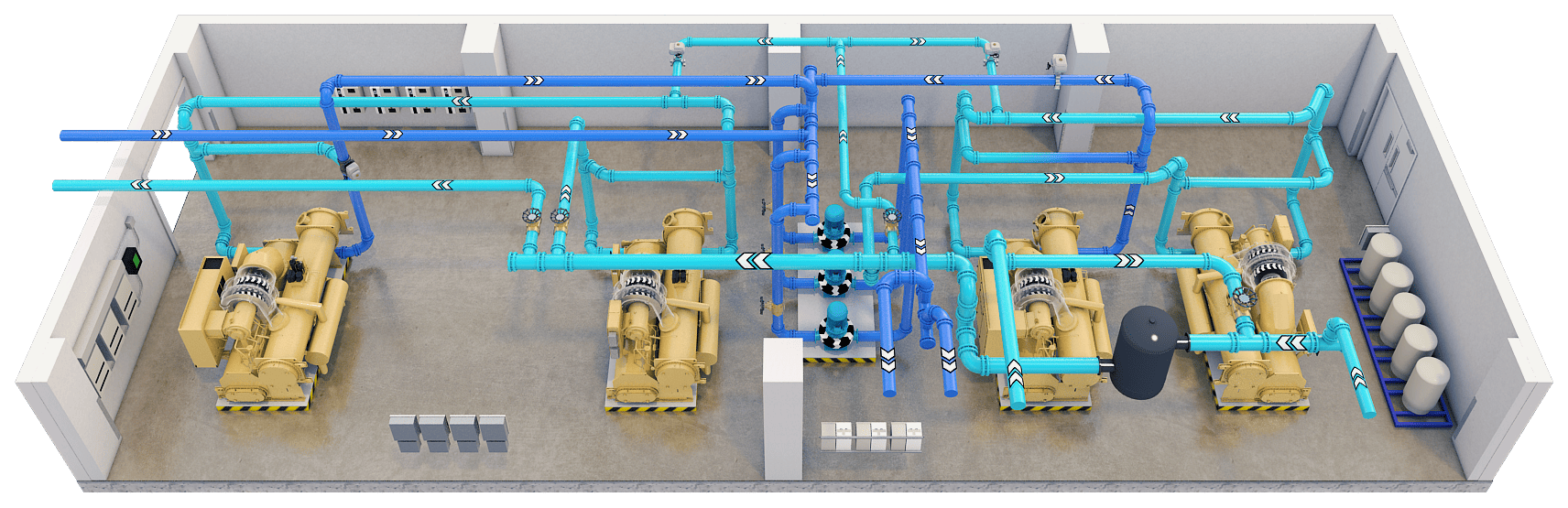
The chiller pipeline system works by circulating a chilled fluid (usually water or a glycol-water mixture) through a closed-loop network. Here’s a simplified overview of the process:
This continuous loop ensures that the system consistently maintains the desired temperature in the facility or process.
Determine the cooling load to establish the required flow rate of the chilled water. This depends on factors such as the size of the building, the type of space being cooled, and the heat gains from occupants, equipment, and external sources.
Proper pipe sizing is essential to ensure efficient water flow and minimize pressure losses. Oversized pipes can be more expensive and require more insulation, while undersized pipes can lead to higher friction losses and reduced system efficiency. Calculations should be based on the desired flow rate, velocity, and acceptable pressure drop.
Common materials for chiller piping include steel, copper, and plastic (such as PVC or CPVC). The choice of material depends on factors such as cost, durability, corrosion resistance, and the nature of the fluid being transported.
The design must consider whether the system will use a primary-only, primary-secondary, or primary-secondary-tertiary configuration. These configurations affect the flow and control of chilled water and are chosen based on system size, complexity, and control requirements.
Control valves, such as two-way or three-way valves, are used to regulate the flow of chilled water based on the cooling demand. Variable speed pumps can also be used to adjust flow rates dynamically, improving energy efficiency.
Consideration must be given to thermal expansion and contraction of pipes due to temperature changes. Expansion joints or loops may be needed to accommodate these changes and prevent stress on the piping system.
Proper insulation of chilled water pipes is essential to prevent heat gain, reduce energy loss, and avoid condensation. The insulation thickness and material should be selected based on the temperature difference between the chilled water and the surrounding environment.
Adequate support and hangers must be provided to ensure the stability and integrity of the piping system. Supports should be spaced appropriately and designed to handle the weight of the pipes and the fluid they carry.
Air vents should be installed at high points in the piping system to remove trapped air, which can impede flow and reduce efficiency. Drain valves should be placed at low points to facilitate draining for maintenance or repairs.
Pressure relief valves should be installed to protect the system from overpressure conditions. These valves are typically placed at critical points, such as near the chiller and in high-pressure zones.